Build your own Guitar
(New page: Category:Gear Let's ROCK!!! == Introduction. == OK, ever felt like you want to 'build' your own Guitar, to your own Specs, but didn't thi...) |
(→The Neck.) |
||
| (8 intermediate revisions not shown.) | |||
| Line 3: | Line 3: | ||
== Introduction. == | == Introduction. == | ||
| + | '''By Sensible Jones.'''<br> | ||
| + | <br> | ||
OK, ever felt like you want to 'build' your own Guitar, to your own Specs, but didn't think you had the skills??<br> | OK, ever felt like you want to 'build' your own Guitar, to your own Specs, but didn't think you had the skills??<br> | ||
Well, I'm here to tell you that '''ANYONE''', with just a little bit of time and patience and a few basic Tools, is capable of producing their own ''''Custom Creation'!!'''<br> | Well, I'm here to tell you that '''ANYONE''', with just a little bit of time and patience and a few basic Tools, is capable of producing their own ''''Custom Creation'!!'''<br> | ||
| Line 56: | Line 58: | ||
== The Body. == | == The Body. == | ||
| - | Let's start with the Body. In this build I used one that I've had for 15 years or so and has been built and rebuilt several times. The first thing I needed to do was to fill in all the Holes left from previous Scratchplates. The best and easiest way to do this is to sharpen some Matchsticks with your Craft Knife, dip them into some PVA Adhesive and then push them into the Holes. Wait until the PVA has dried (it goes clear) and then cut | + | Let's start with the Body. In this build I used one that I've had for 15 years or so and has been built and rebuilt several times. The first thing I needed to do was to fill in all the Holes left from previous Scratchplates. The best and easiest way to do this is to sharpen some Matchsticks with your Craft Knife, dip them into some PVA Adhesive and then push them into the Holes. Wait until the PVA has dried (it goes clear) and then cut off the remainder with your Wirecutters, as close as you can to the surface of the Body. You will leave a small 'nipple' of PVA and matchstick which can be carefully removed, flush with the Body, by using a sharp Wood Chisel.<br> |
I also decided to 'sheild' the control cavity using some self-adhesive Copper Sheet. Here you can see the Matches stuck in and the shielding applied:-<br> | I also decided to 'sheild' the control cavity using some self-adhesive Copper Sheet. Here you can see the Matches stuck in and the shielding applied:-<br> | ||
[[Image:Shielding2.jpg]]<br> | [[Image:Shielding2.jpg]]<br> | ||
| Line 82: | Line 84: | ||
<br> | <br> | ||
Start by installing the Pots. When you receive the Pots they will have a small fixing Nut and Washer attached to them, remove these first and push the Splined shaft through the hole in the Scratchplate from the rear. Your scratchplate will probably have a shielding sheet on the backside, just push the shaft through it. Then reattach the washer and then the nut, tighten in place with a spanner. You'll notice that this scratchplate has a small hole by each of the main Pot holes, these are for a small locating lug on each of the Pots. Not all Pots have these!<br> | Start by installing the Pots. When you receive the Pots they will have a small fixing Nut and Washer attached to them, remove these first and push the Splined shaft through the hole in the Scratchplate from the rear. Your scratchplate will probably have a shielding sheet on the backside, just push the shaft through it. Then reattach the washer and then the nut, tighten in place with a spanner. You'll notice that this scratchplate has a small hole by each of the main Pot holes, these are for a small locating lug on each of the Pots. Not all Pots have these!<br> | ||
| - | Attach the Pickup Selector Switch with the screws provided and then attach the Pickups themselves. Remember to install the Spring over each of the pickup screws!!!<br> | + | Attach the Pickup Selector Switch with the screws provided and then attach the Pickups themselves. Remember to install the Spring over each of the pickup screws!!! This will need your No 1 Phillips Screwdriver.<br> |
<br> | <br> | ||
Now, to the actual wiring itself!!<br> | Now, to the actual wiring itself!!<br> | ||
| Line 89: | Line 91: | ||
It should look something like this:-<br> | It should look something like this:-<br> | ||
[[Image:Strat Wiring.jpg]]<br> | [[Image:Strat Wiring.jpg]]<br> | ||
| + | Use your Gas Soldering Iron to solder to the Tabs on the Pots and your 100W to solder to the Pot Cases. If you try to use too small a Soldering Iron to Solder the 'Grounds' and Capacitor Legs to the Pot cases you may well damage the Pot's internal workings!! | ||
In the top diagram there is only 1 Capacitor and in the picture there are 2, one on each Tone Pot. I prefer using 2 as it gives a slightly better and smoother tonal response, but whichever you decide is your own prerogative!<br> | In the top diagram there is only 1 Capacitor and in the picture there are 2, one on each Tone Pot. I prefer using 2 as it gives a slightly better and smoother tonal response, but whichever you decide is your own prerogative!<br> | ||
| - | Next, join all three 'Grounds' from your pickups and solder to the casing of the first Tone Pot (or the Volume Pot it will all be grounded anyway!) then solder the relevant 'Hot' wire from each Pickup to it's relevant place on the Switch | + | Next, join all three 'Grounds' from your pickups and solder to the casing of the first Tone Pot (or the Volume Pot it will all be grounded anyway!) then solder the relevant 'Hot' wire from each Pickup to it's relevant place on the Switch using your smaller Soldering Iron, especially on these PCB typ switches!!! Now you should have something like this:-<br> |
[[Image:RW Split option.jpg]]<br> | [[Image:RW Split option.jpg]]<br> | ||
As I used Rail Type Humbuckers I have two wires left over!! The Red and White. (Which are used if you want to make your Pickups Coil Tapped.)<br> | As I used Rail Type Humbuckers I have two wires left over!! The Red and White. (Which are used if you want to make your Pickups Coil Tapped.)<br> | ||
| Line 115: | Line 118: | ||
'''Don't''' screw the scratchplate down just yet!!!!!<br> | '''Don't''' screw the scratchplate down just yet!!!!!<br> | ||
<br> | <br> | ||
| - | Insert the Neck into the Pocket as hard and tight as you can, now line up the Scratchplate to the Neck and Bridge and screw in position!<br> | + | Insert the Neck into the Pocket as hard and tight as you can, now line up the Scratchplate to the Neck and Bridge and screw in position using your No 1 Phillips Screwdriver! You can also screw down the Jack Socket as well.<br> |
<br> | <br> | ||
| + | |||
== The Neck. == | == The Neck. == | ||
There's not too much to tell you here as it all depends on how you buy your neck, with or without hardware and whatever design you want. This one is obviously from a left-handed instrument originally so I had to fill the original fixing holes in the Heel. I did this the same was as I filled the Body holes but just used bigger 'plugs'. I also had to re-drill the holes for the machineheads as this originally had 'Vintage' style tuners (which utilise a 6mm hole) and I wanted to install a set of modern style ones (which need an 8mm hole.) These holes were re-drilled on a Pillar Drill to make sure everything was kept square.<br> | There's not too much to tell you here as it all depends on how you buy your neck, with or without hardware and whatever design you want. This one is obviously from a left-handed instrument originally so I had to fill the original fixing holes in the Heel. I did this the same was as I filled the Body holes but just used bigger 'plugs'. I also had to re-drill the holes for the machineheads as this originally had 'Vintage' style tuners (which utilise a 6mm hole) and I wanted to install a set of modern style ones (which need an 8mm hole.) These holes were re-drilled on a Pillar Drill to make sure everything was kept square.<br> | ||
These machineheads (Wilkinson's) have a small 'Locating Pin' on them and so,once the holes were drilled, the machineheads were pushed through from the back and the point for the locator was marked for each Tuner. I then pre-drill a small hole to suit for each locator. The Machineheads were then all pushed into place and the Sleeve Nut that secures them in place was tightened using the appropriate sized spanner.<br> | These machineheads (Wilkinson's) have a small 'Locating Pin' on them and so,once the holes were drilled, the machineheads were pushed through from the back and the point for the locator was marked for each Tuner. I then pre-drill a small hole to suit for each locator. The Machineheads were then all pushed into place and the Sleeve Nut that secures them in place was tightened using the appropriate sized spanner.<br> | ||
| - | Unfortunately I don't have pics of this whole process as I'd already completed it all before I decided to write this article and once these type of tuners are in place they are quite difficult to remove. Other types have a small screw instead of the locator Pin and are a lot easier to remove.<br | + | Unfortunately I don't have pics of this whole process as I'd already completed it all before I decided to write this article and once these type of tuners are in place they are quite difficult to remove. Other types have a small screw instead of the locator Pin and are a lot easier to remove.<br> |
[[Image:Headstock Back.JPG ]]<br> | [[Image:Headstock Back.JPG ]]<br> | ||
[[Image:Headstock front.JPG]]<br> | [[Image:Headstock front.JPG]]<br> | ||
| Line 142: | Line 146: | ||
== The Final Assembly. == | == The Final Assembly. == | ||
| - | Right, we're almost there!!!! The finishing line is in sight!! Push the neck into it's Pocket as hard and as tight as possible. Turn over, being careful not to dislodge the neck. You may find this easier to have someone help you keep the two bits tight together. Place the Neckplate in position on the back of the Body and attach the neck using the four screws. It looks like there are two Neckplates in my first photo but one of them is a thin Plastic tray that the Neckplate sits in, this stops the Plate from marking and indenting the Wood.<br> | + | Right, we're almost there!!!! The finishing line is in sight!! Push the neck into it's Pocket as hard and as tight as possible. Turn over, being careful not to dislodge the neck. You may find this easier to have someone help you keep the two bits tight together. Place the Neckplate in position on the back of the Body and attach the neck using the four screws. It looks like there are two Neckplates in my first photo but one of them is a thin Plastic tray that the Neckplate sits in, this stops the Plate from marking and indenting the Wood. (Not all Neckplates are supplied with this plastic tray.)<br> |
[[Image:Tremolo attached.JPG]]<br> | [[Image:Tremolo attached.JPG]]<br> | ||
<br> | <br> | ||
Current revision
Contents |
Introduction.
By Sensible Jones.
OK, ever felt like you want to 'build' your own Guitar, to your own Specs, but didn't think you had the skills??
Well, I'm here to tell you that ANYONE, with just a little bit of time and patience and a few basic Tools, is capable of producing their own 'Custom Creation'!!
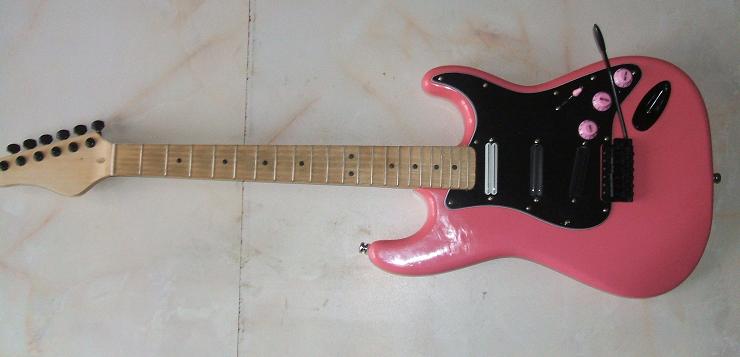
In this article I'll take you through the assembly of the Guitar pictured on the right.>>>>>>>
As you can see it's a Strat styled instrument and so we'll be using a Vintage style Tremolo Bridge and 3 pickups with 1 Volume and 2 Tone controls. The whole process is exactly the same, whether you are building a Tele, a V, a Les Paul etc! It doesn't matter what shape it is, it will still have the same basic geometry and parts!!!
So, what do you need to get started???
All the bits you'll need!
Well, Tools-wise you'll need:-
Phillips Screwdrivers. (No 1 and No 2.)
Soldering Iron. (Preferably 2!! A 100 Watt and a small Gas Type)
Pre-fluxed Solder.
Wirecutters.
Pliers.
Craft Knife.
Steel Rule or straight Edge.
Allen Keys.
PVA Adhesive.
A sharp Wood Chisel.
A Drill. (A hand drill will suffice.)
A 3 or 3.5 Drill Bit. (For predrilling the Neck Screw Holes.)
As for the parts, well where to start?????
Basically you'll need:-
A Body.
A Neck.
Tuners. (Machineheads, Tuning Pegs.)
Neckplate.
Pickups.
Scratchplate.
Pots.
0.22mf capacitor. (Or 2)
Bridge.
5 Way Selector Switch.
Jack Socket.
Some Single Core 0.25mm Wire. (Can also be multi-Core, but I prefer single Core)
Some 0.25 or 0.5mm 'Shielded' Wire.
Control Knobs and Switch Tip.
Copper shielding.
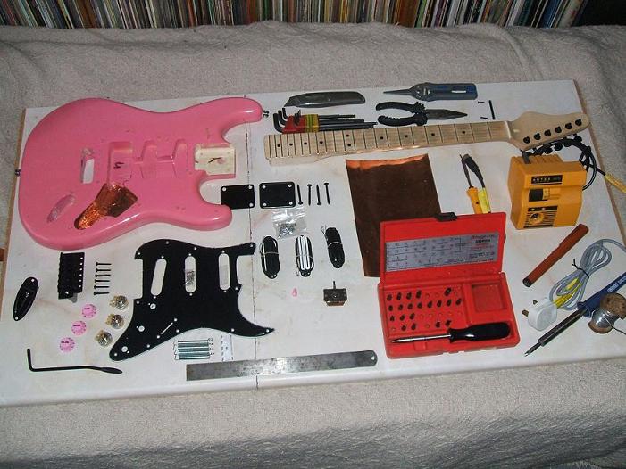
Looks a little daunting doesn't it??
Fear not, it's really not that difficult!!!
Let's get started!
The Body.
Let's start with the Body. In this build I used one that I've had for 15 years or so and has been built and rebuilt several times. The first thing I needed to do was to fill in all the Holes left from previous Scratchplates. The best and easiest way to do this is to sharpen some Matchsticks with your Craft Knife, dip them into some PVA Adhesive and then push them into the Holes. Wait until the PVA has dried (it goes clear) and then cut off the remainder with your Wirecutters, as close as you can to the surface of the Body. You will leave a small 'nipple' of PVA and matchstick which can be carefully removed, flush with the Body, by using a sharp Wood Chisel.
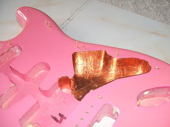
I also decided to 'sheild' the control cavity using some self-adhesive Copper Sheet. Here you can see the Matches stuck in and the shielding applied:-
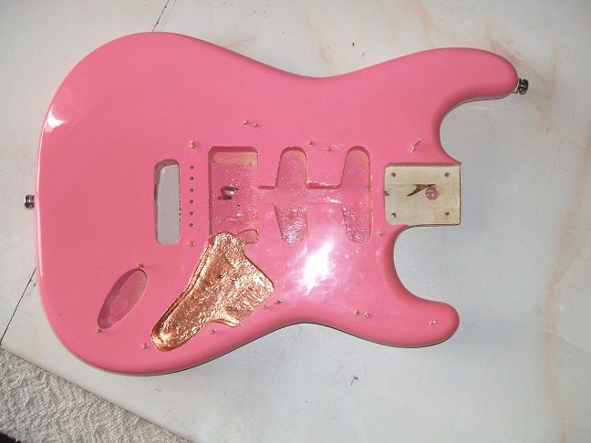
To do the shielding you will need to get some self-adhesive Copper sheet. It is also available in Tape form of varying widths. I use the sheet form so that I can cut it down to whatever width I need.

Using you steel rule measure the depth of the Cavity and, using your rule and Craft Knife, cut enough strips to go around the vertical surface of the Cavity. Once you have done that cut some more strips to cover the bottom of the cavity. Cut whatever shapes you need to cover it completely, it doesn't matter at all if your pieces overlap!!
Here you can clearly see the shielding and matches in place:-
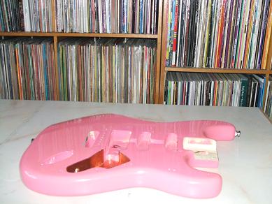
And here you can see that I've trimmed the matches down and used the Chisel to get the surface flush again:-
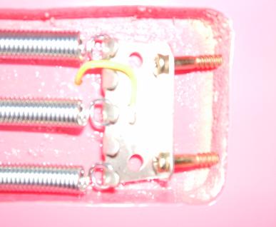
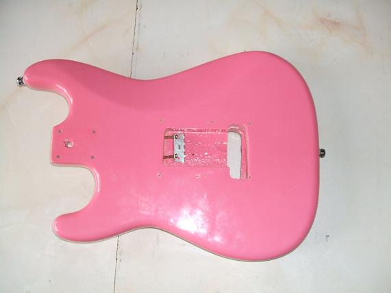
Now, turn the Body over and attach the Spring retaining Claw for the Tremolo. The easiest way to do this is to push the Claw against the front edge of the Cavity and about central depthwise. Mark the two screw holes with a Pencil and remove the Claw. Screw the two screws into the marks at a slight angle into the Body. If you try to screw them in parallel then it makes it harder to access them later for adjusting the spring tension!!!
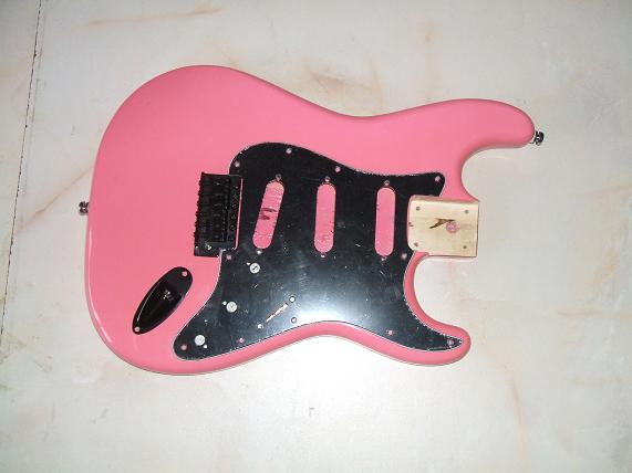
Turn the Body back over and attach the Bridge with the screws provided. At this point I always like to make sure that everything all fits properly and looks good. Here it is with the Bridge attached and the Scratchplate and Jack Socket just resting in place:-
OK, take a deep breath as next we move onto.......
The Wiring.
First off I'd like to say DON'T BE SCARED!!!
I knew nothing about this kind of Electronics when I built my first guitar, BUT with a little patience and methodical working it's really quite straighforward and you don't even have to really understand the theory of Electronics! As long as you follow the Wiring Diagram at the end you can't go wrong!!!
Here's all the parts laid out:-
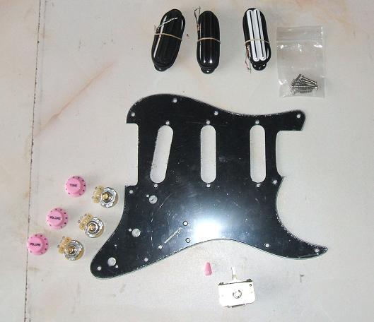
Start by installing the Pots. When you receive the Pots they will have a small fixing Nut and Washer attached to them, remove these first and push the Splined shaft through the hole in the Scratchplate from the rear. Your scratchplate will probably have a shielding sheet on the backside, just push the shaft through it. Then reattach the washer and then the nut, tighten in place with a spanner. You'll notice that this scratchplate has a small hole by each of the main Pot holes, these are for a small locating lug on each of the Pots. Not all Pots have these!
Attach the Pickup Selector Switch with the screws provided and then attach the Pickups themselves. Remember to install the Spring over each of the pickup screws!!! This will need your No 1 Phillips Screwdriver.
Now, to the actual wiring itself!!
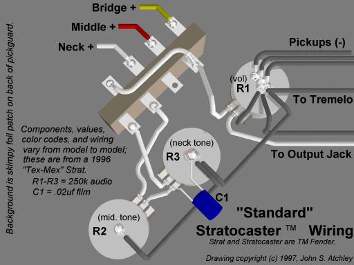
Refer to the Wiring Diagram below. Using the 0.25 Single Core wire connect your Switch to the Volume and Tone Pots as illustrated:-
It should look something like this:-
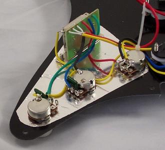
Use your Gas Soldering Iron to solder to the Tabs on the Pots and your 100W to solder to the Pot Cases. If you try to use too small a Soldering Iron to Solder the 'Grounds' and Capacitor Legs to the Pot cases you may well damage the Pot's internal workings!!
In the top diagram there is only 1 Capacitor and in the picture there are 2, one on each Tone Pot. I prefer using 2 as it gives a slightly better and smoother tonal response, but whichever you decide is your own prerogative!
Next, join all three 'Grounds' from your pickups and solder to the casing of the first Tone Pot (or the Volume Pot it will all be grounded anyway!) then solder the relevant 'Hot' wire from each Pickup to it's relevant place on the Switch using your smaller Soldering Iron, especially on these PCB typ switches!!! Now you should have something like this:-
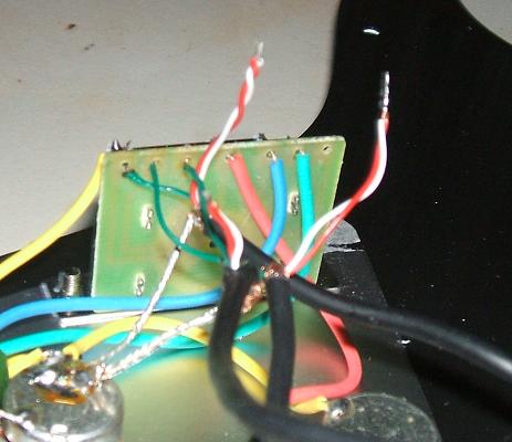
As I used Rail Type Humbuckers I have two wires left over!! The Red and White. (Which are used if you want to make your Pickups Coil Tapped.)
The wiring code for these particular ones is:-
Hot = Green. (Connect to Switch.)
Ground = Black and Bare. (Soldered together and then to the Tone Pot.)
Red and White = Coil Split option. (Not being used so just tape them up and out of the way.)
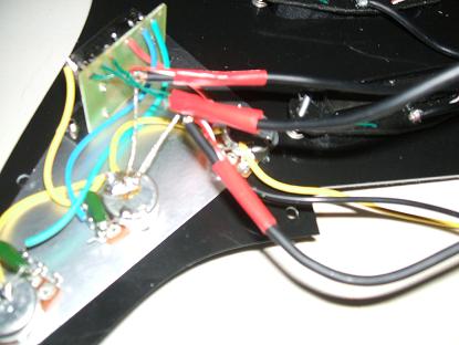
Next, solder a length of Single Core to the Ground of whichever Pot you decided on, this will be a Ground wire to be soldered to your Spring Claw in the back of the Guitar. Now strip the end of the Shielded Wire, about an inch long will be sufficient. Pull away the shielding and twist together. This end can now undergo what is called 'Tinning'. Heat it up with your Soldering Iron and when hot enough run some solder into it thus binding all the strands of the shield together and making it a lot easier to solder to the relevant place. Strip back a small bit of the insulation of the centre wire and 'Tin' this end too. Solder the shield to the case of either the Volume or Tone Pot (whichever you used) and the Wire to the Centre tag of the Volume Pot. This shielded Wire is your output to the Jack Socket.
The Yellow 'tail' is the Claw Ground Wire and the Black 'tail' is the Output wire.
To make it easier to install I use small 'Cable Ties/Zip Ties' to tidy the wiring up and also to get the Pickup wires central. This can save a lot of aggravation when trying to install the Scratchplate!!!!

(If you're never going to change your Pickups you can cut the wires to length when you install them to make it even tidier!)
Now, push the single Core wire through the small hole in the body and through to the tremolo cavity and the Shielded Wire through the Hole into the Jack Socket Cavity. (Both these holes should be pre-drilled.)
Solder the Single Core to the Spring Claw and install the Springs.
Connect the Jack Socket by soldering the Centre Wire to the tab that will connect with the Tip of your Cable and the Shield to the Sleeve Tab.
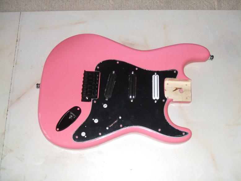
Don't screw the scratchplate down just yet!!!!!
Insert the Neck into the Pocket as hard and tight as you can, now line up the Scratchplate to the Neck and Bridge and screw in position using your No 1 Phillips Screwdriver! You can also screw down the Jack Socket as well.
The Neck.
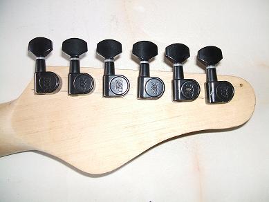
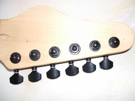
There's not too much to tell you here as it all depends on how you buy your neck, with or without hardware and whatever design you want. This one is obviously from a left-handed instrument originally so I had to fill the original fixing holes in the Heel. I did this the same was as I filled the Body holes but just used bigger 'plugs'. I also had to re-drill the holes for the machineheads as this originally had 'Vintage' style tuners (which utilise a 6mm hole) and I wanted to install a set of modern style ones (which need an 8mm hole.) These holes were re-drilled on a Pillar Drill to make sure everything was kept square.
These machineheads (Wilkinson's) have a small 'Locating Pin' on them and so,once the holes were drilled, the machineheads were pushed through from the back and the point for the locator was marked for each Tuner. I then pre-drill a small hole to suit for each locator. The Machineheads were then all pushed into place and the Sleeve Nut that secures them in place was tightened using the appropriate sized spanner.
Unfortunately I don't have pics of this whole process as I'd already completed it all before I decided to write this article and once these type of tuners are in place they are quite difficult to remove. Other types have a small screw instead of the locator Pin and are a lot easier to remove.
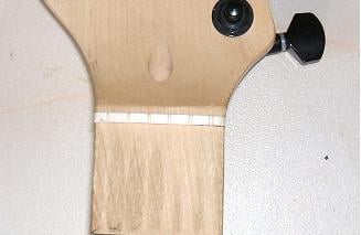
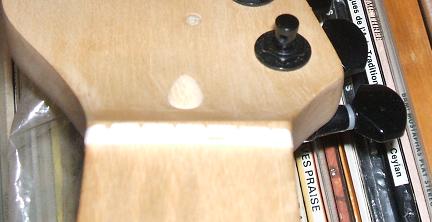
I also needed to reverse the Nut so that the larger, low E string slot was where the 'top' of the neck would now be.
Here it is in it's original position:-
And here it is turned around:-
This was done by gently prising it out of it's slot using a very thin Flat-bladed Screwdriver.
Now, once you have gotten this far, push the Neck tightly into the Neck Pocket on the Body and mark and predrill the four screwholes.
Make sure not to drill all the way through the Fingerboard!!!
A good trick here is to mark the drill bit with a piece of Tape at the right depth and then just drill until the Tape is just touching the Neck!
Now you've got this far it's time for......
The Final Assembly.
Right, we're almost there!!!! The finishing line is in sight!! Push the neck into it's Pocket as hard and as tight as possible. Turn over, being careful not to dislodge the neck. You may find this easier to have someone help you keep the two bits tight together. Place the Neckplate in position on the back of the Body and attach the neck using the four screws. It looks like there are two Neckplates in my first photo but one of them is a thin Plastic tray that the Neckplate sits in, this stops the Plate from marking and indenting the Wood. (Not all Neckplates are supplied with this plastic tray.)
Now you can put your Control Knobs and Switch Tip on and GUESS WHAT???
That's it!!! You've built your first Guitar!!!!

Now I know what you're all thinking.....
And that's "But Sensible, you've forgotten something!! How am I going to play it with no Strings???"
Well my friends, it's like this, I'm going to String it and set it up, String Height, Intonation etc in a follow-up article!!!
Hope you enjoyed getting this far and if you have any questions and queries don't hesitate to ask either in the Forums or via PM!!!
So, until the next exciting episode.......
--Sensible Jones 16:34, 30 October 2009 (CET)
